


Preliminary steps
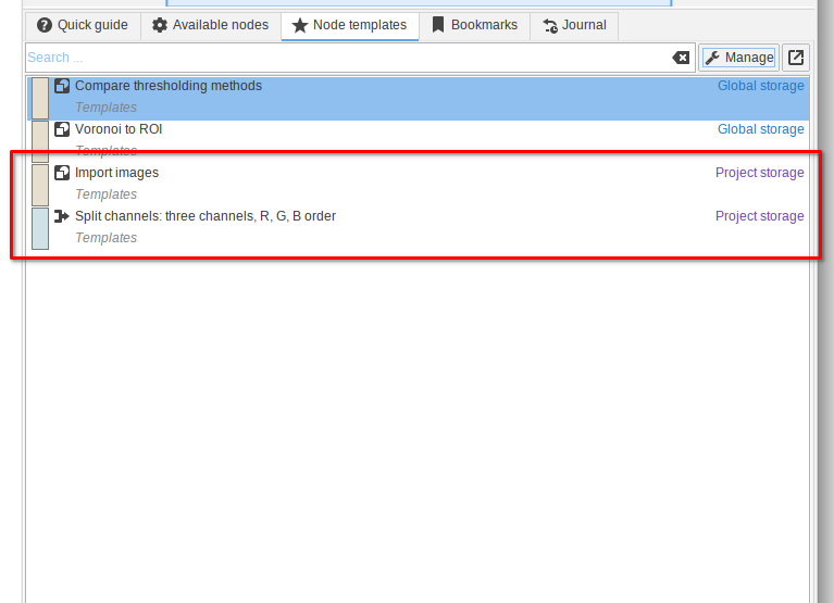
👉 This tutorial requires that you have installed two node templates Split channels: three channels, R, G, B order and Import images.
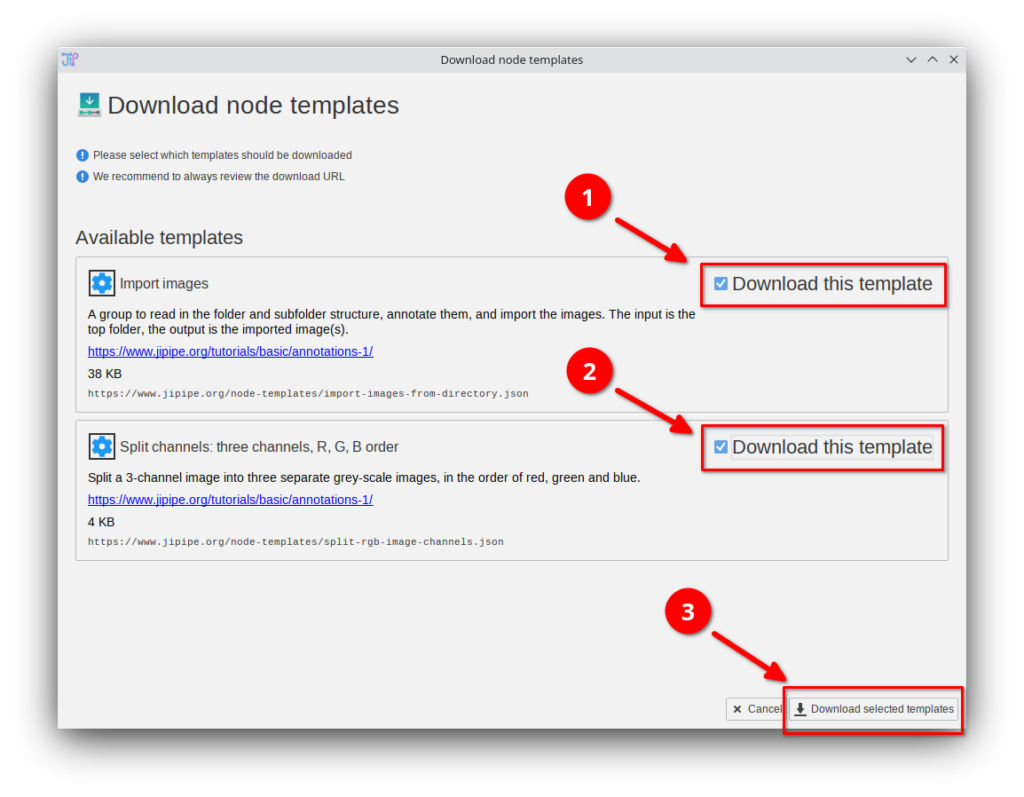
If you do not have these templates, you can download them via Manage > Download more templates or by importing the Templates.json file that is provided in the data package. If you do not know how to download or import node templates, please check out our tutorial.

Step 1
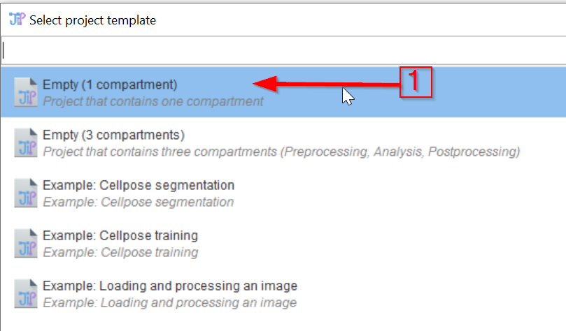
Create a new JIPipe project (red arrow 1) using a template (red arrow 2).
Step 2
Chose a template with one compartment.
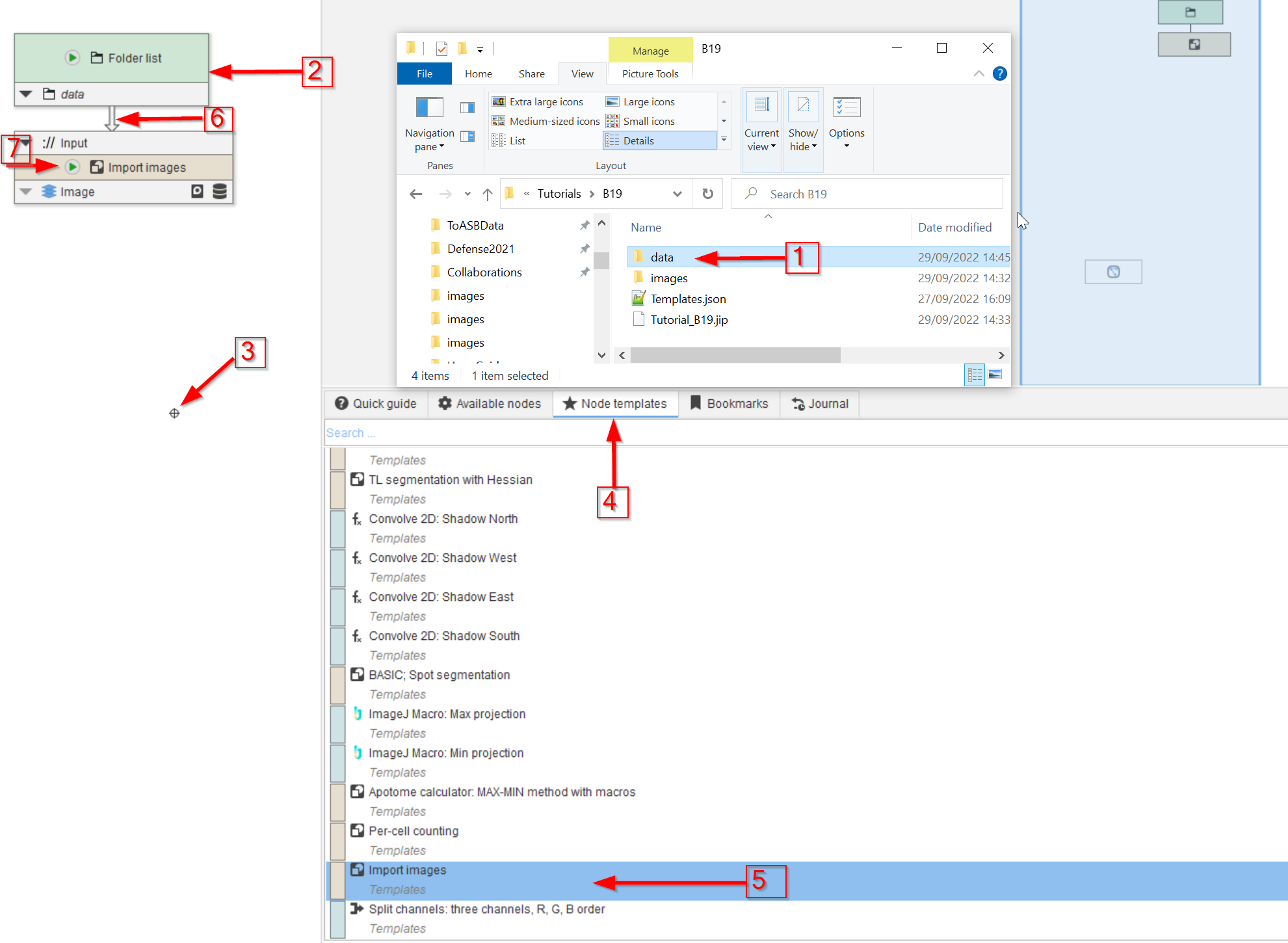
Step 3
Locate the data folder that belongs to this tutorial (red arrow 1) and drop it on the UI (red arrow 2).
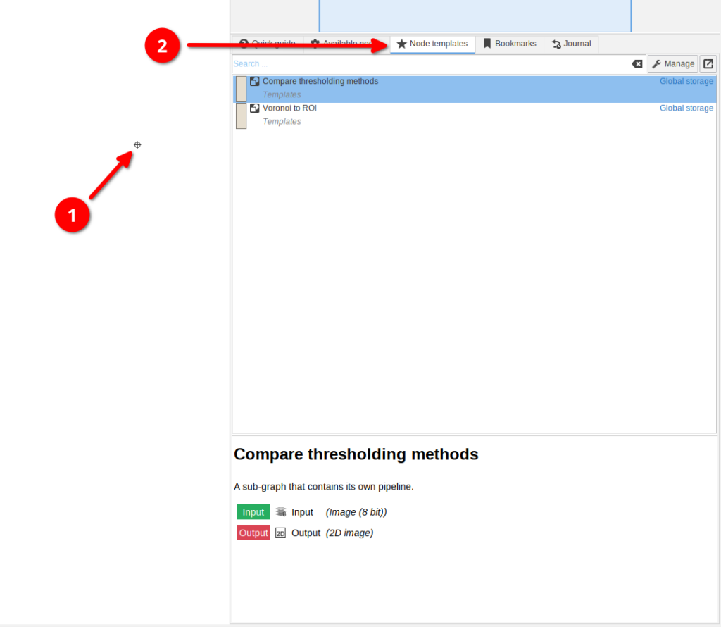
Click somewhere on the white area of the UI (red arrow 3) and choose the Node templates tab (red arrow 4).
Select the pre-made Import images template from the list (red arrow 5) and drag it to the UI.
Connect it to the Folder list node (red arrow 6) and run the Import images node via the Update cache command (red arrow 7.)
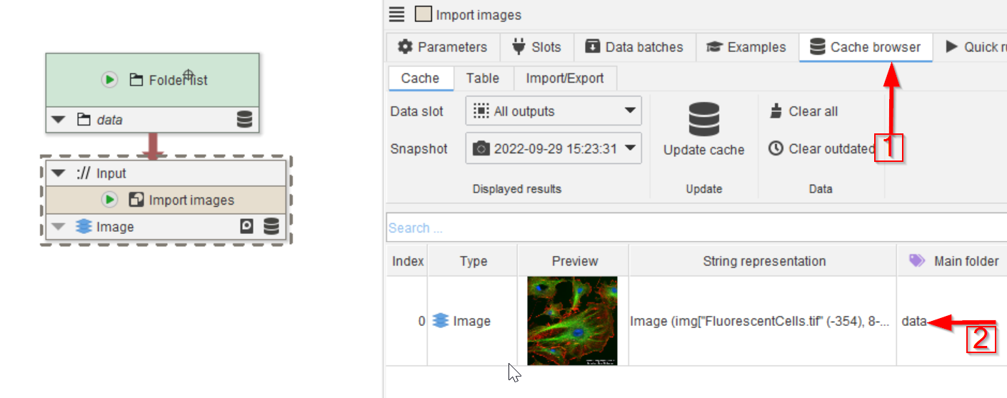
Step 4
The Cache browser (red arrow 1) will now show the fluorescence image (red arrow 2).
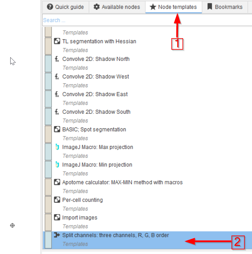
Step 5
Next navigate to the Node templates tab (red arrow 1) and drag the Split channels: three channels R, G, B order template (red arrow 2) onto the graph.
Connect the newly created node to the output of Import images.
Step 6
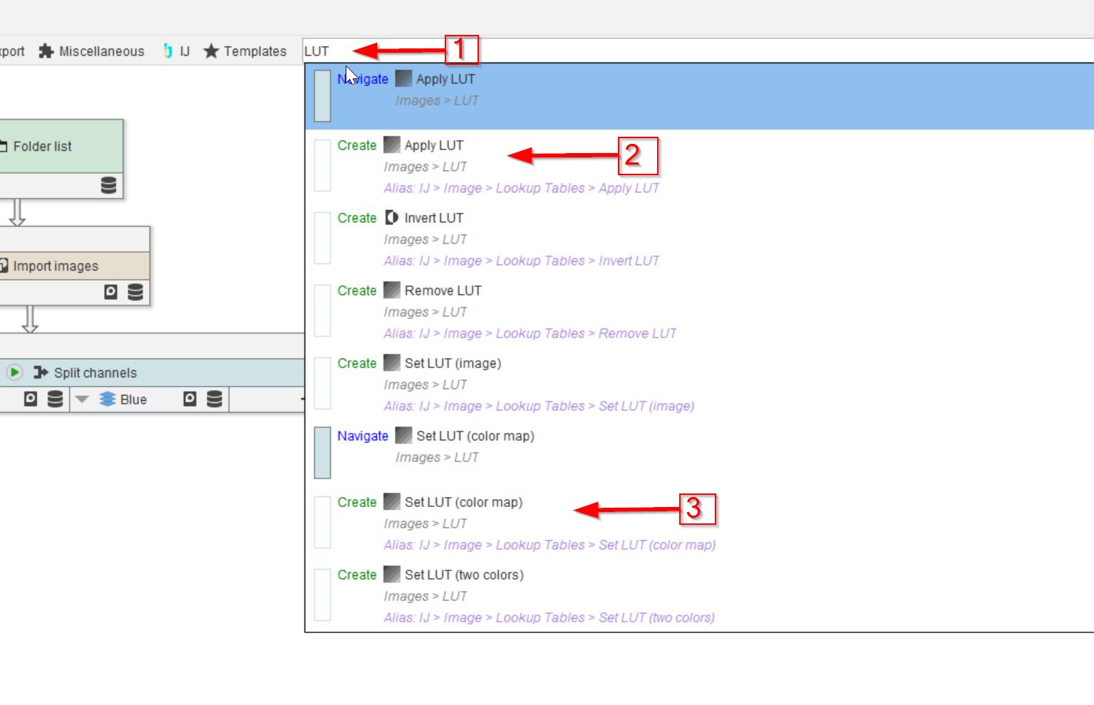
We will now apply a look-up table (LUT) to one of the channels.
To do this, use the search bar (red arrow 1) to add the following nodes:
Set LUT (color map)(red arrow 3)Apply LUT(red arrow 2)
Connect the input of Set LUT (color map) node to the Red output of Split channels: three channels R, G, B order.
Then connect the output of Set LUT (color map) to the input of Apply LUT
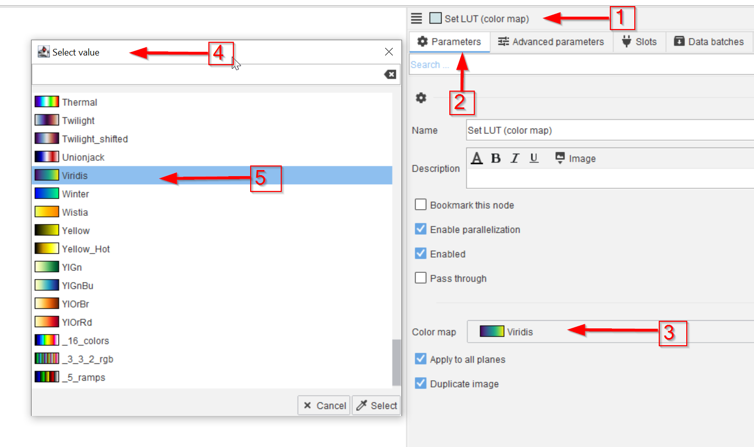
Step 7
Select the Set LUT (color map) node (red arrow 1) and go to the Parameters tab (red arrow 2). Proceed to and activate the Color map field (red arrow 3).
In the Select value window (red arrow 4), chose the desired look-up table, e.g. Viridis (red arrow 5).
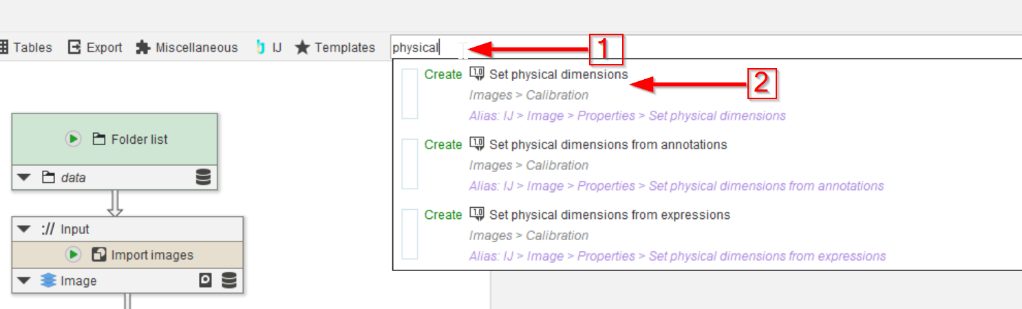
Step 8
To change the pixel size and other physical dimensions of an image, search for nodes with the keyword physical (red arrow 1). Select the Set physical dimensions node (red arrow 2).
Step 9
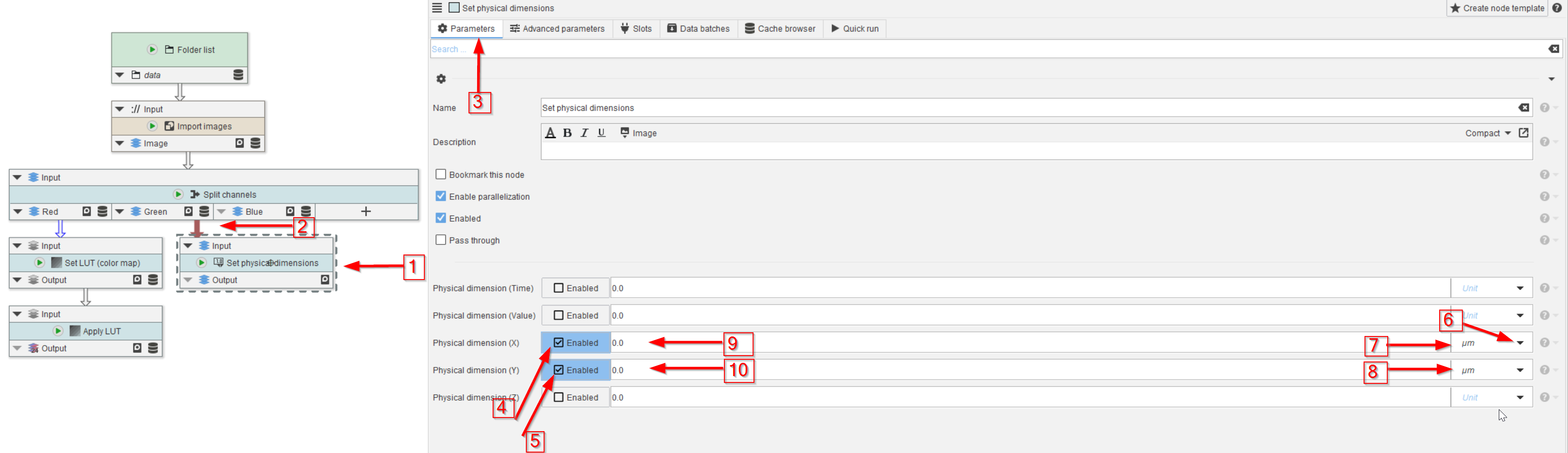
Drag the new node to the UI (red arrow 1) and connect it to, e.g., the Green channel of the Split channels node (red arrow 2).
In the Parameters menu (red arrow 3), enable the physical dimensions that need to be changed (red arrows 4, 5).
From the drop-down list (red arrow 6) choose the proper dimensions (red arrows 7, 8). The values can be entered in the neighboring fields (red arrows 9, 10).
For this example, set X and Y pixel dimensions both to 1.0 micrometer (1 µm).
Step 10
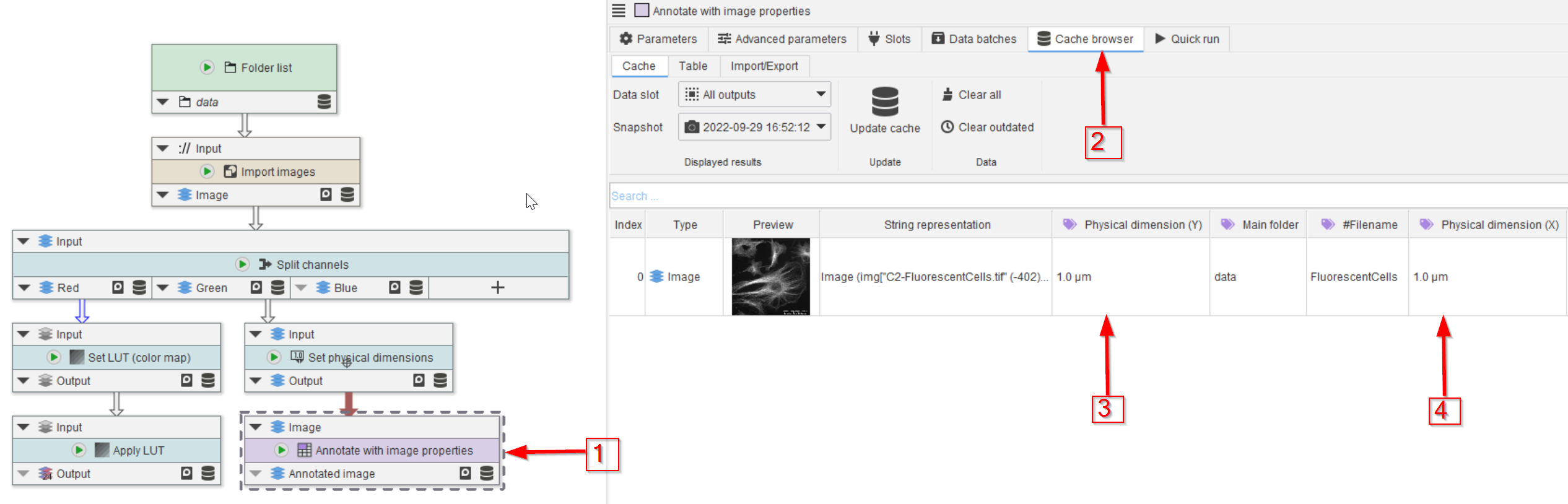
Read out the physical dimensions of the newly calibrated image by adding a node Annotate with image properties (red arrow 1) and connecting it to the output of Set physical dimensions.
Run the node and observe the Cache browser (red arrow 2). Now both the X and Y dimensions are added to the annotations table (red arrows 3 and 4).