Handling multi-channel images I
Explains the process of splitting channels, RGB conversion, channel coloring, and adding comments with image information.
Tutorial: Handling multi-channel images I
Step 1
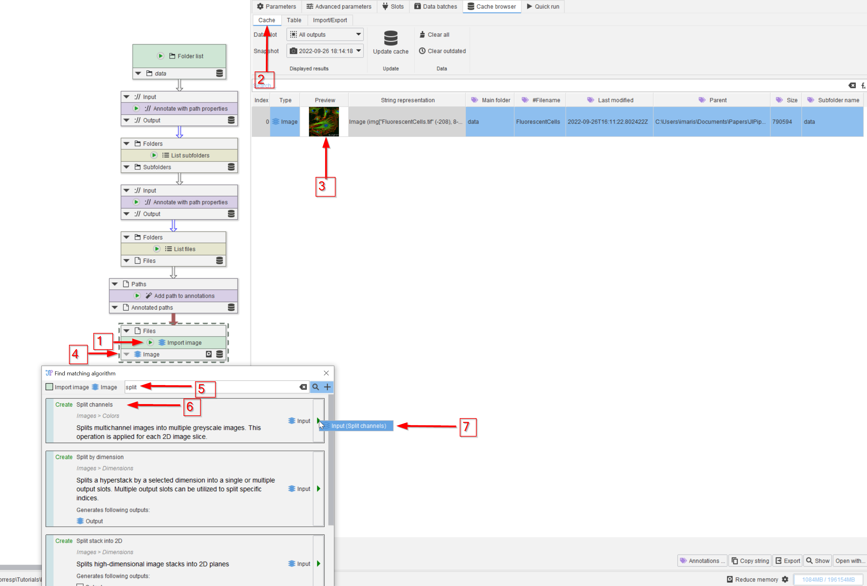
Open the project file and run the bottom node Import image (red arrow 1). Chose the Cache intermediate results option to see the outcome from all nodes.
Observe the cache (red arrow 2) and notice that the image has multiple channels (red arrow 3). In order to split the channels, search for a suitable node (red arrow 4) with the keyword split (red arrow 5). Choose the Split channels node (red arrow 6) and add it to the pipeline (red arrow 7).
The Split channels node behaves exactly as its equivalent from ImageJ (channel splitter).
Step 2
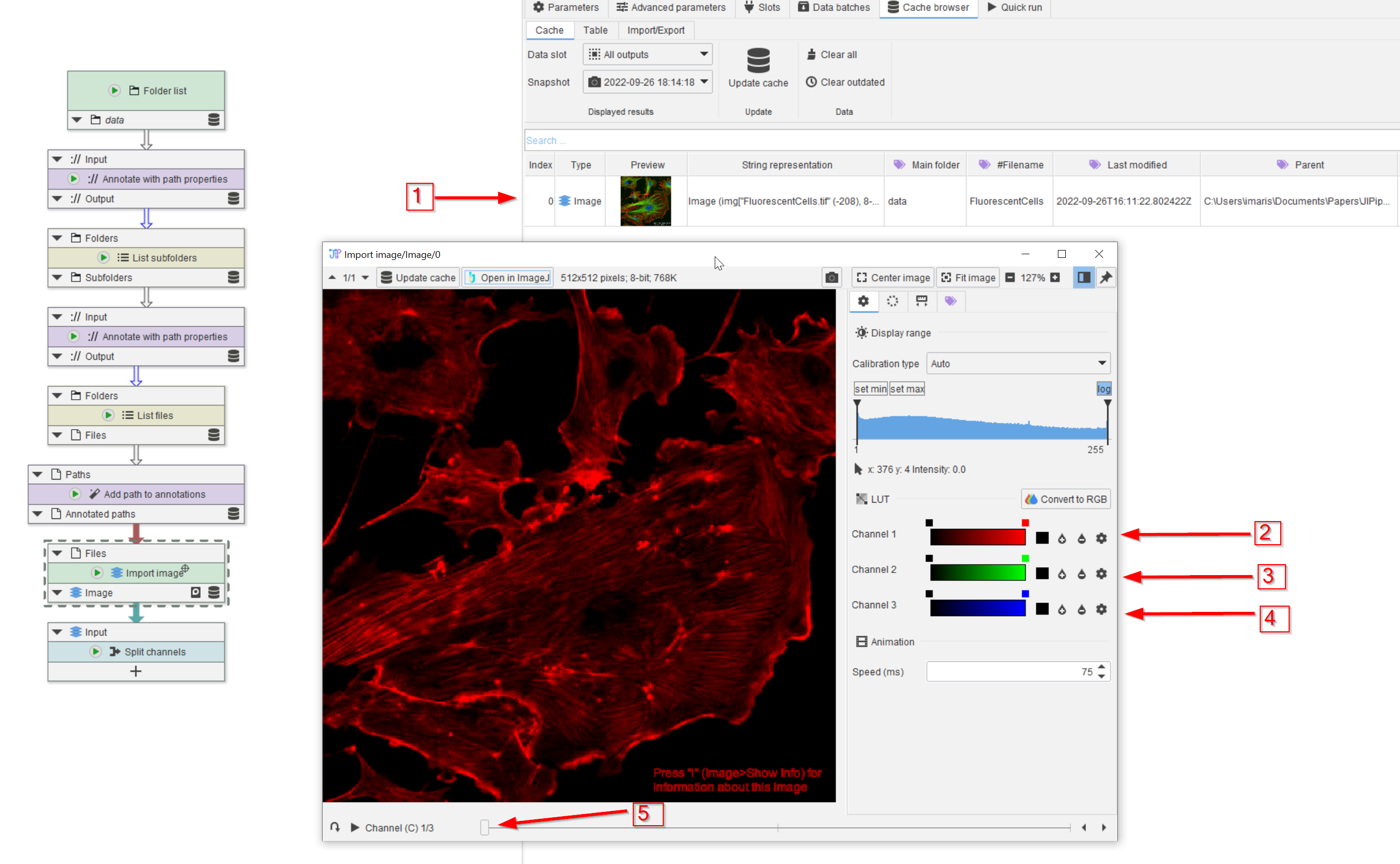
The number of channels can be easily figured out from the image viewer. Double click on the image in the cache of the Import image node (red arrow 1) and note the three listed channels (red arrows 2, 3, 4).
In the image viewer, the channels can be selected via a slider (red arrow 5).
Step 3
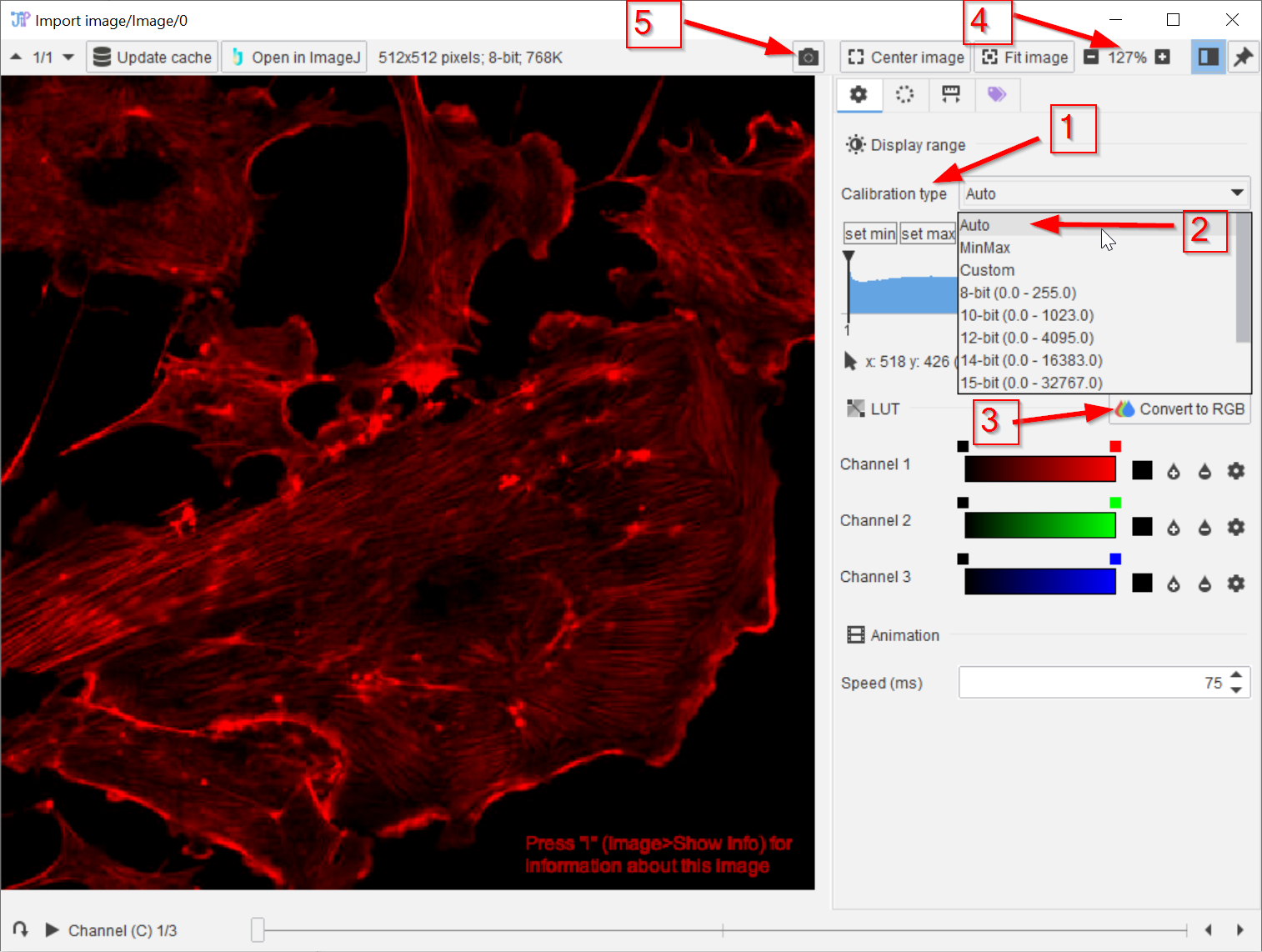
The image contrast can be selected from a list (red arrow 1), using Auto (red arrow 2) is the default setting. The multichannel image can be converted into an RGB image (red arrow 3), whereas the zoom factor can be set via a +/- button set (red arrow 4). The resulting image can be exported or copied into the system cache as described before (red arrow 5).
Basic information about the image (resolution, bit depth, etc.) can be found in the toolbar of the image viewer and within the “String representation” column in the cache browser.
Step 4
The image will be split into three channels, as revealed by the image viewer.
To set up the Split channels node, we need to add three output channels, corresponding to the red, green, and blue channels of the raw image:
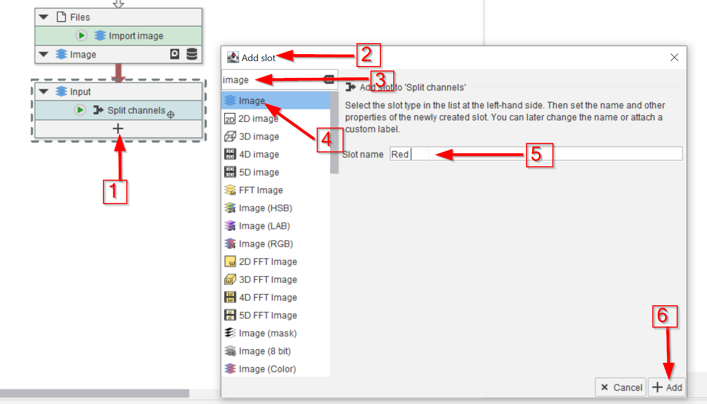
click on the ➕ sign to add a new slot to the Split channels node (red arrow 1). This will open the Add slot window (red arrow 2), where we search for image as data type (red arrow 3).
It’s not necessary to be more specific about the image format, the general Image type (red arrow 4) will take care of any conversion automatically. We name the first channel Red (red arrow 5) and add the new slot (red arrow 6).
The Split channels node has a configurable outputs; each corresponding to one output channel. There are various nodes that have configurable inputs and/or outputs.

Step 5
The Split channels node can be set up from the Parameters menu.
By repeating the red channel addition for green and blue, we end up with the necessary three-channel output (red arrows 1, 2, 3). The output channels are assigned to those of the incoming image, starting the channel counting at zero (red arrows 4, 5, 6). The new channel indices and names are added to the annotation system (red arrows 7, 8).
Pre-made examples for 2-channel and 3-channel splitting are available in the Examples tab.
Step 6
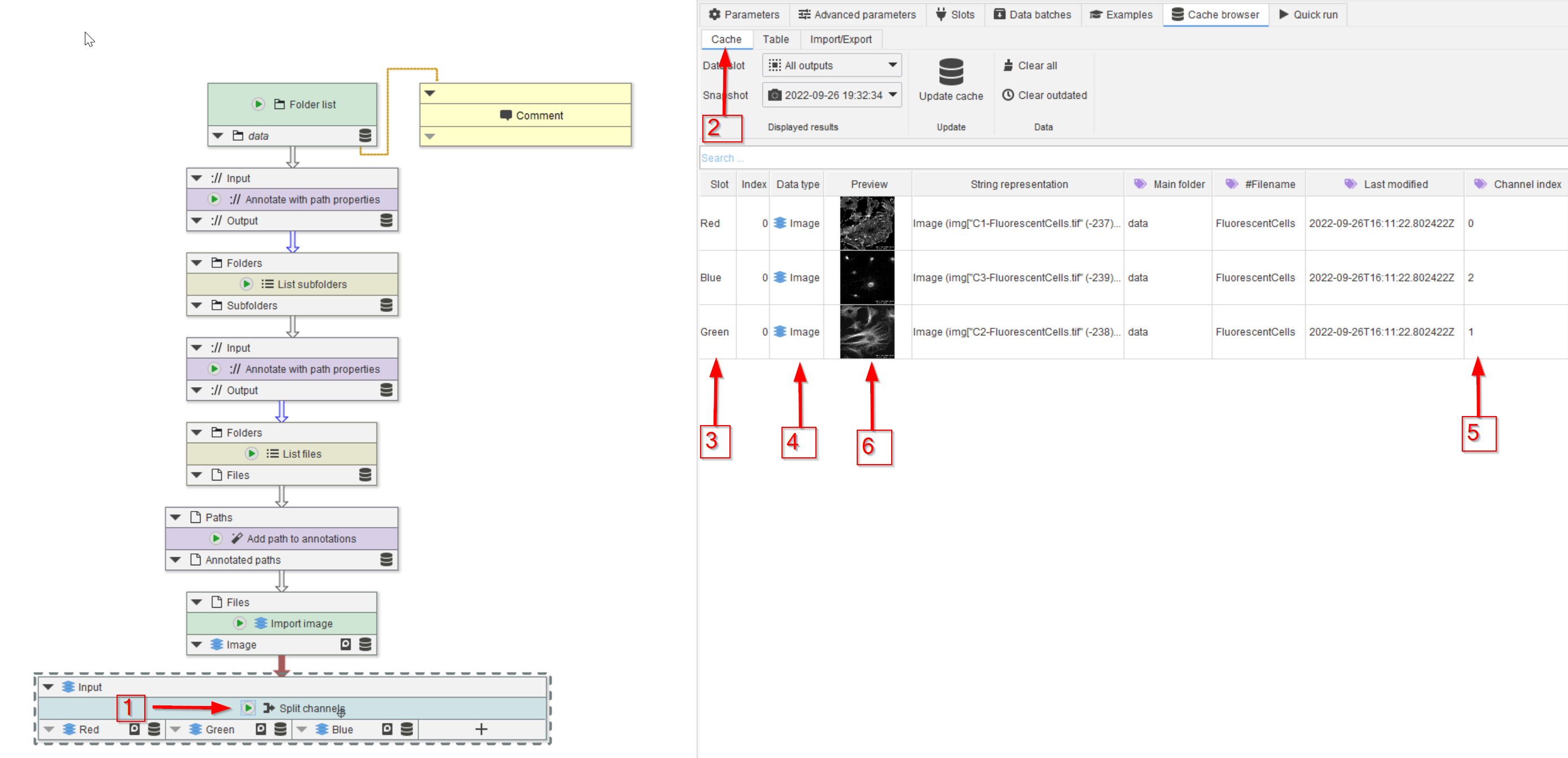
Run the Split channels node (red arrow 1) and observe the cache (red arrow 2).
The slot name (red arrow 3), data type (red arrow 4) and channel index (red arrow 5) are now shown as annotations, in addition to the three images on grey scale (red arrow 6).