Compartments I: Creating and connecting
Explains how to segment pipelines into compartments and transfer data between them
Tutorial: Compartments I (Creating and connecting)
Step 1
Load the example pipeline. The output of the workflow is the three channels of the FluorescentCells image, and the single channel of the blobs image.
Before we start processing these images, we shall separate the processing nodes from the preprocessing nodes. The latter includes the steps that we have entered until now: folder structure, annotations, image import, image filtering based on annotations, and channel splitting (if necessary). It is easier to organize the pipeline if we now start a new work place as introduced earlier when we discussed compartments.
Compartments segment the pipeline into organizational units. The difference between groups and compartments is that groups are separate pipelines and thus subject to limitations.
Compartments on the other hand are are feature of the JIPipe GUI to segment the main project pipeline.
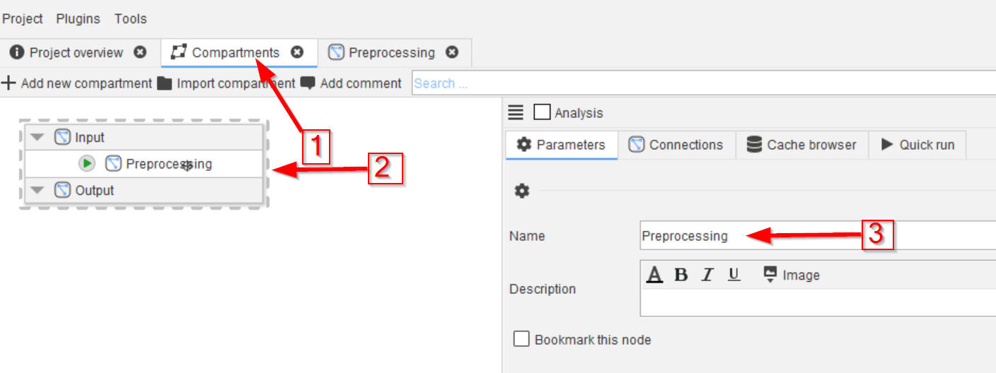
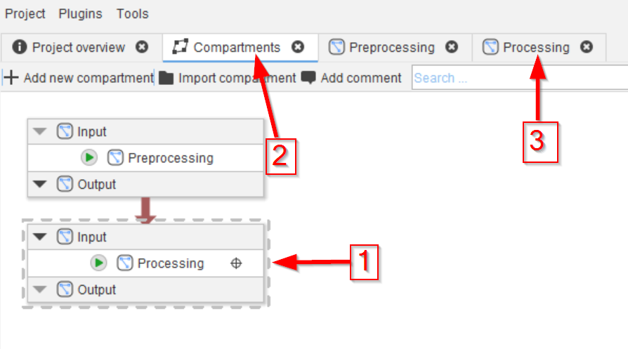
Begin by navigating to the Compartments tab (red arrow 1) and renaming the Analysis compartment (red arrow 2) to Preprocessing (red arrow 3).
Step 2
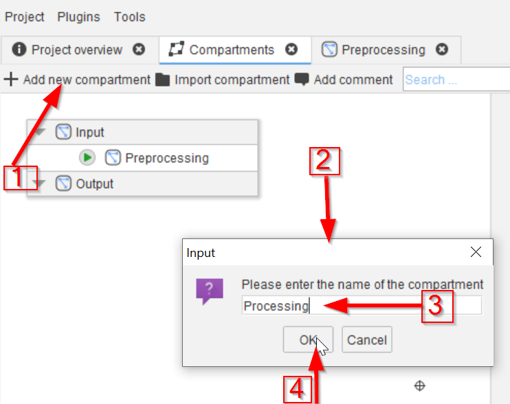
Click on the Add new compartment button (red arrow 1) and use the Input window (red arrow 2) to add a new compartment Processing (red arrow 3).
Click OK to add the new compartment to the GUI (red arrow 4).
Step 3
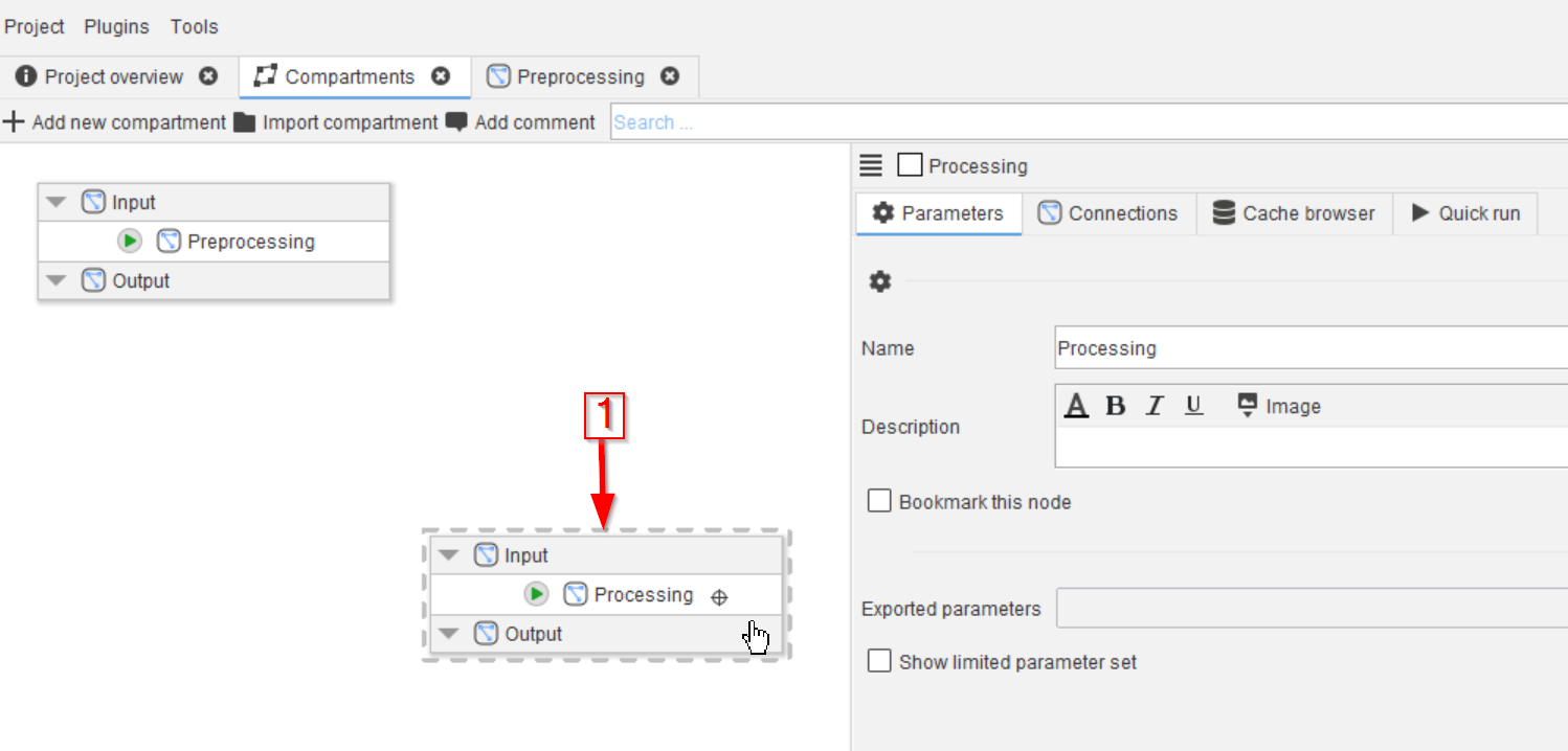
The new compartment will now appear on the GUI (red arrow 1).
Step 4
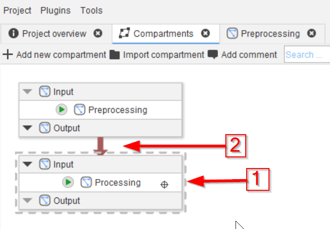
Reposition the new node (red arrow 1) and connect it to the Preprocessing compartment (red arrow 2).
👉 This connection will transfer the data from the Preprocessing compartment to the new Processing compartment via the built-in output and input nodes of the compartments. These still need to be set up, which we will do next.
Step 5
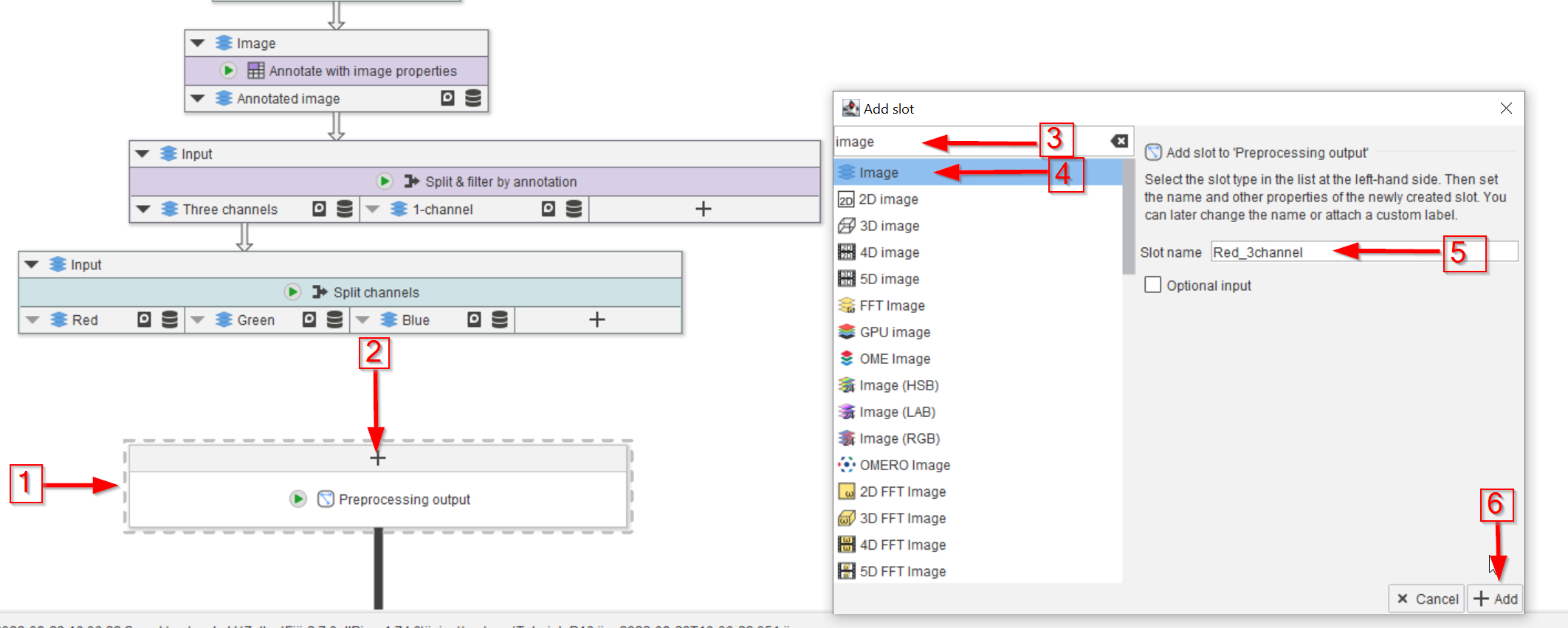
Go to the Preprocessing compartment by double-clicking the its node and locate the Preprocessing output node (red arrow 1).
Move the node close to the rest of the nodes, click on the ➕ button to add a new input slot (red arrow 2). The input type should be an image, so use image as a search word (red arrow 3). The Image type will now be selected (red arrow 4) and the new slot will be given a name (red arrow 5).
Click Add when the editing is done (red arrow 6).
Each compartment contains a xyz output node that acts as interface to transfer data to other compartments.
{{ /notice }}
Step 6
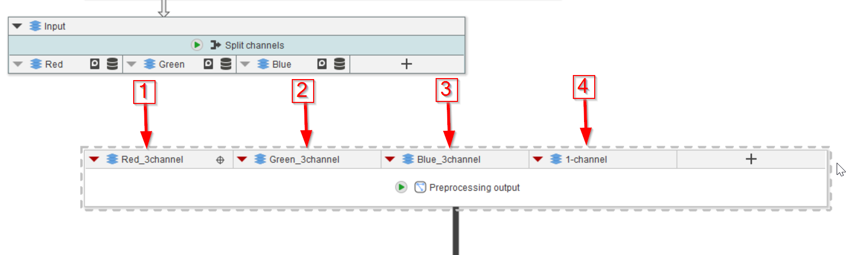
Now the new input slot of the Preprocessing output node will appear (red arrow 1).
Repeat the same process for the next three input slots, one each for the green and blue fluorescence channel and for the single channel of the blob image (red arrows 2 to 4).
Please ensure that the following slots are present in the Preprocessing output node:
Red_3channel(type should be Image)Green_3channel(type should be Image)Blue_3channel(type should be Image)1-channel(type should be Image)
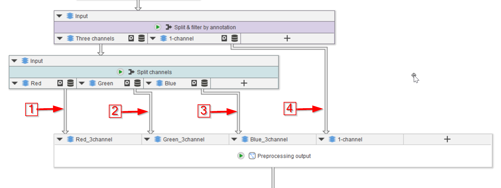
Step 7
Connect the corresponding outputs from the two nodes above (red arrows 1-4).
Step 8
Now the Preprocessing compartment will emit these images as output.
The connection to the Processing compartment will absorb these images as Input. This can be observed by double-clicking on the Processing compartment (red arrow 1) in the Compartments tab (red arrow 2), to reveal the content inside the compartment node (red arrow 3).
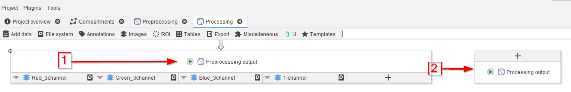
Step 9
The nodes inside the Processing compartment contain the output node from Preprocessing (red arrow 1), and the output node of the Processing compartment (red arrow 2).