Measurements
The filament toolkit can calculate measurements for vertices, edges, and filament components.

Measuring vertices
Use the Measure filament vertices node to extract the measurements of all vertices into a table. The following measurements will be generated:
| The unique identifier of the vertex |
|---|---|
| The X location of the vertex centroid in pixels |
| The Y location of the vertex centroid in pixels |
| The Z location of the vertex centroid in pixels |
| The Channel location of the vertex |
| The Frame location of the vertex |
| The vertex radius in pixels |
| The vertex value (numeric) |
| The vertex color (Hex string), for example |
| The vertex degree |
| The physical voxel size in X direction, for example |
| The physical voxel size in Y direction, for example |
| The physical voxel size in Z direction, for example |
Metadata keys | Additional columns are added based on available vertex metadata keys. The columns are named according to the metadata key. The column contains numbers if all vertex metadata values can be converted into numbers, otherwise the column contains strings. |
Value backups | If you stored vertex value backups, they will be placed into columns |
Measuring edges
Use the Measure filament edges node to generate a results table containing edge measurements.
The table will have the following structure:
| The unique identifier of the vertex |
|---|---|
| The edge color (Hex string), for example |
| The edge length (in pixels) |
| The edge length (in physical size if available) |
| The unit of physical sizes (consensus unit that is calculated over all vertices) |
| All measurements of the source vertex, but the columns are prefixed with |
| All measurements of the target vertex, but the columns are prefixed with |
Metadata keys | Additional columns are added based on available edge metadata keys. The columns are named according to the metadata key. The column contains numbers if all edge metadata values can be converted into numbers, otherwise the column contains strings. |
Measuring filament components
Use the Measure filament components node to generate measurements for each filament component.
The table will have one row per component and has the following structure:
| Numerical component id (starting with zero) |
|---|---|
| The number of vertices in the component |
| The number of edges in the component |
| The sum of all edge lengths (in pixels) |
| The sum of all edge lengths (in physical unit) |
| The sum of all edge lengths (in pixels). Learn more about radius correction here. |
| The sum of all edge lengths (in physical unit). Learn more about radius correction here. |
| The sum of all edge lengths (in pixels) of the simplified graph. |
| The sum of all edge lengths (in physical unit) of the simplified graph. |
| The sum of all edge lengths (in pixels) of the simplified graph. Additional radius correction is applied. |
| The sum of all edge lengths (in physical unit) of the simplified graph. Additional radius correction is applied. |
| The confinement ratio calculated by: |
| The confinement ratio calculated by: |
| Number of vertices with degree zero (single vertices). |
| Number of vertices with degree one (end points). |
| Number of vertices with degree two (line segments). |
| Number of vertices with degree three. |
| Number of vertices with degree four. |
| Number of vertices with degree five. |
| Number of vertices with degree six or higher. |
| The maximum degree over all vertices in the component. |
| The minimum degree over all vertices in the component. |
| The minimum per-vertex centroid X over all vertices in the component, in pixels. Learn more about bounding box measurements here. |
| The minimum per-vertex centroid Y over all vertices in the component, in pixels. Learn more about bounding box measurements here. |
| The minimum per-vertex centroid Z over all vertices in the component, in pixels. Learn more about bounding box measurements here. |
| The maximum per-vertex centroid X over all vertices in the component, in pixels. Learn more about bounding box measurements here. |
| The maximum per-vertex centroid Y over all vertices in the component, in pixels. Learn more about bounding box measurements here. |
| The maximum per-vertex centroid Z over all vertices in the component, in pixels. Learn more about bounding box measurements here. |
| The minimum per-vertex X (including the radius) over all vertices in the component, in pixels. Learn more about bounding box measurements here. |
| The minimum per-vertex Y (including the radius) over all vertices in the component, in pixels. Learn more about bounding box measurements here. |
| The minimum per-vertex Z (including the radius) over all vertices in the component, in pixels. Learn more about bounding box measurements here. |
| The maximum per-vertex X (including the radius) over all vertices in the component, in pixels. Learn more about bounding box measurements here. |
| The maximum per-vertex Y (including the radius) over all vertices in the component, in pixels. Learn more about bounding box measurements here. |
| The maximum per-vertex Z (including the radius) over all vertices in the component, in pixels. Learn more about bounding box measurements here. |
| The centroid (X coordinate) of the whole filament component, in pixels. |
| The centroid (Y coordinate) of the whole filament component, in pixels. |
| The centroid (Z coordinate) of the whole filament component, in pixels. |
| The centroid (Channel coordinate) of the whole filament component. |
| The centroid (Frame coordinate) of the whole filament component. |
| The minimum edge length (in pixels). |
| The minimum edge length (in physical unit). |
| The maximum edge length (in pixels). |
| The maximum edge length (in physical unit). |
| The average edge length (in pixels). |
| The average edge length (in physical unit). |
| The minimum vertex radius (in pixels). |
| The minimum vertex radius (in physical unit). |
| The maximum vertex radius (in pixels). |
| The maximum vertex radius (in physical unit). |
| The average vertex radius (in pixels). |
| The average vertex radius (in physical unit). |
| The minimum vertex value. |
| The maximum vertex value. |
| The average vertex value. |
| The consensus physical size unit. |
Radius correction
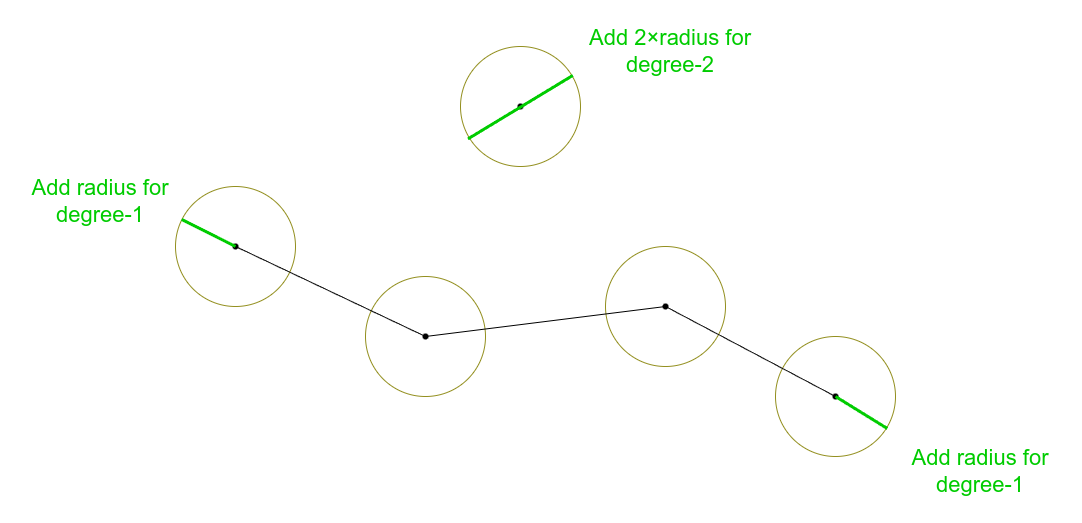
Classic length measurement just summarizes the length of all edges. This may yield shorter than expected lengths, as the radius of end points is not considered in the calculations.
Radius-corrected length measurements add the radius of each degree-1 vertex, and twice the radius for degree-0 vertices to the calculated length.

Simplified graph
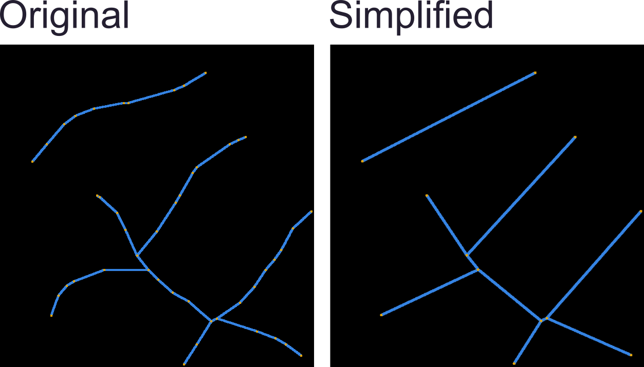
The simplified graph is calculated by skipping all degree-2 vertices and directly connecting the lines. You can explicitly calculate the simplified graph by using the node Simplify filaments.

Bounding box measurements
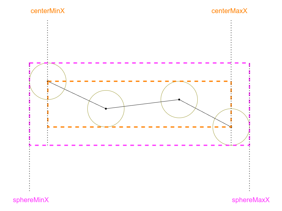
There are two possible bounding box measurements for filaments, one that is based around the vertex center, and another that also incorporates the vertex radius.
The following illustration showcases the difference for the X coordinate:
